
Objective of the Experiment
In this experiment, the goal is to calculate the dielectric constant of material and demonstrate the inversely proportional relationship between the resonance period and the distance between the parallel plates.
1. Theory and Definitions
An insulating material placed between the plates of a capacitor is called a dielectric. Putting a dielectric between the parallel plates of a capacitor will increase its capacitance by decreasing the electric potential difference between the plates.
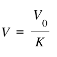
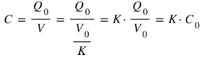
Where V0, Q0, C0 are the initial potential, charge, and capacitance where vacuum is present between plates, and V, Q, and C are the potential, charge, and capacitance where a dielectric is inserted between plates after the capacitor has been disconnected from the battery.
The capacitance of a parallel plate system can be calculated using this relation:
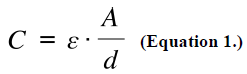
Where C is the capacitance, epsilon is the permittivity of the material, A is the area of a single plate in the system, and d is the margin between plates.
As we know, the permittivity of free space is epsilon0 = 8.854 x 10^-12 and this value is very close to the permittivity of the air at the STP. We can write other material’s permittivities as:
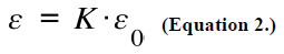
Where K is the dielectric constant of the material. (K = 1 for vacuum and K ~ 1 for air at STP.)
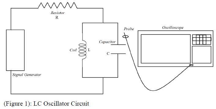
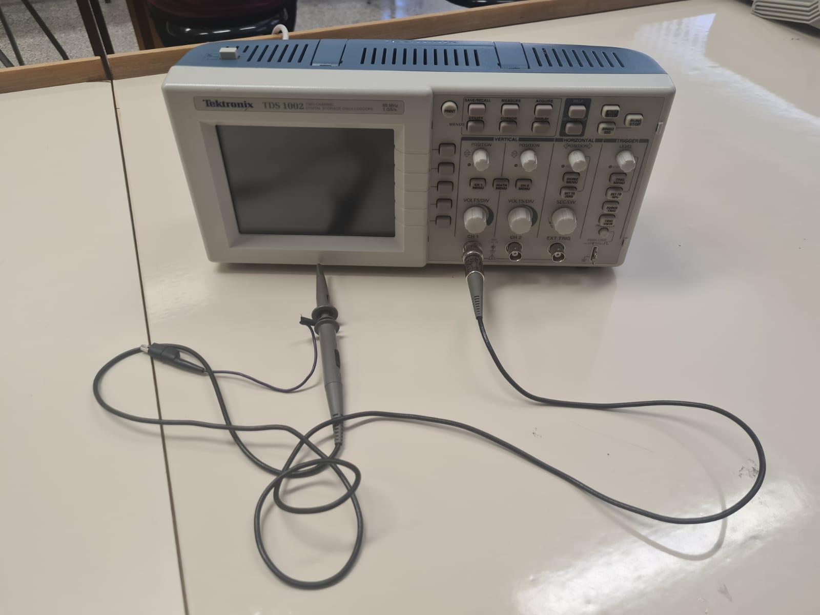
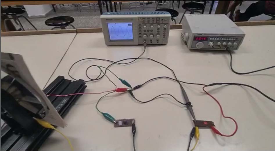
In Figure 1 below, we connect a coil with inductance L in parallel with a capacitor with capacitance C, and then to this parallel connection, we connect a resistor in series with resistance R. We then connect a signal generator in series to create sinusoidal signals, and then monitor and measure the frequency or the period using the oscilloscope.
In an LC Oscillator Circuit, inductive reactance of the coil XL with inductance L can be calculated using:
Similarly, in an LC Oscillator Circuit, capacitor reactance of the capacitor with capacitance C can be calculated using:
Where ω is the angular frequency of the signal generator.
To see how these reactances can help us with calculating the permittivity of a material, we can use a concept called resonance. Electrical resonance occurs in an LC Oscillator Circuit when the impedances of circuit elements (coil and capacitor) cancel each other. In theory, the impedance of the cell is infinite when there is resonance. We can calculate the impedance of the cell (Z) using
If the impedance of the cell is infinite, then,
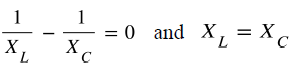
which means
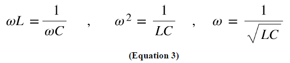
Because we are calculating the angular frequency when there is resonance, we call this angular frequency the resonance frequency, and we can write it in terms of the period of the signal generator:
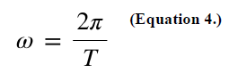
When equation 3 and equation 4 are merged, and the capacitance is given with equation 1 and we write permittivity of the material with equation 2, we attain the equation 5:
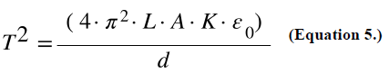
This equation is important for two reasons. Firstly, we can calculate the dielectric constant of the desired material as long as we know the period, reactance of coil, area of the plate, and the distance between plates with equation 6. Secondly, we can observe here that the period and the distance between plates are inversely proportional and T^2 and 1/d are linearly proportional (Observation 1.)
Using observation 1, if we plot the graph of T^2 versus 1/d, we should get a line. And writing K in terms of slope, we get equation 7.
2. Procedure
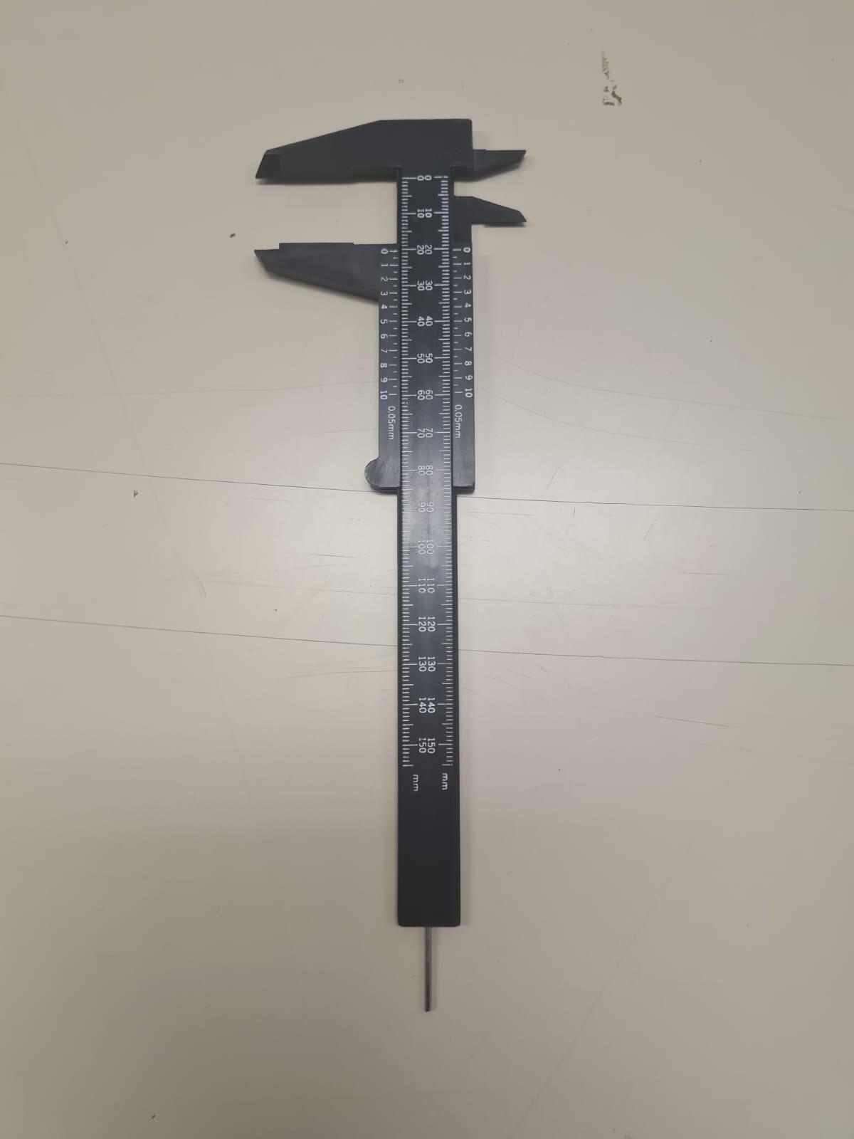
2.1. Equipment
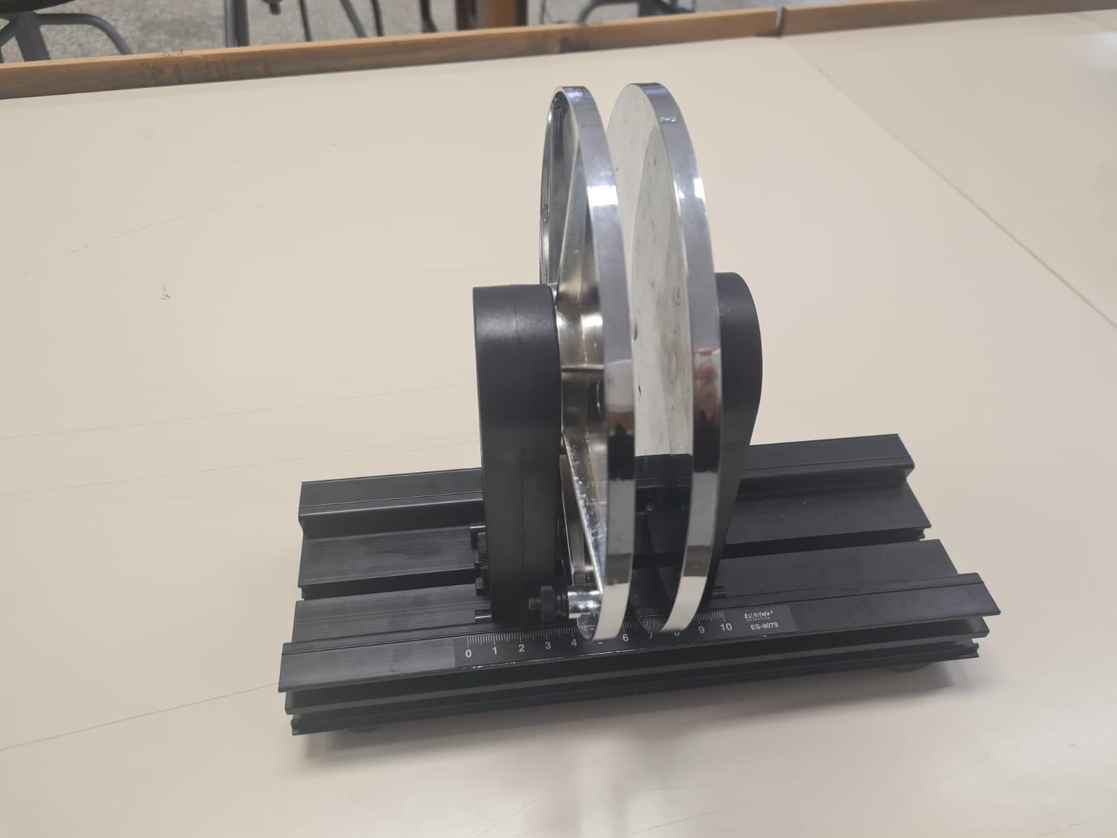
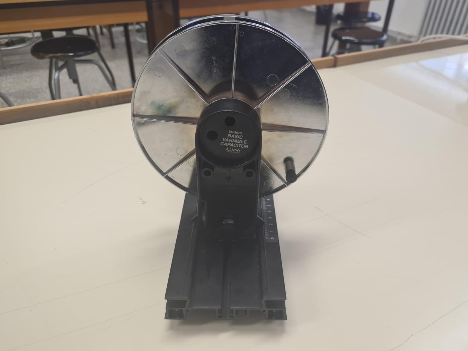

2.2. Set-Up
To set up the figure 1:
-
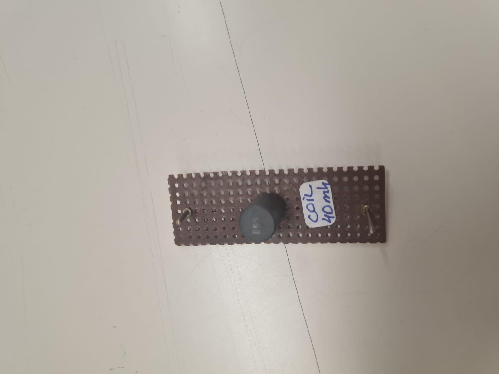
Connect coil and capacitor in parallel.
-
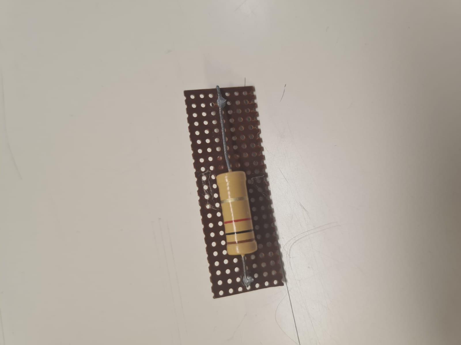
Connect a resistor to the coil and capacitor in series.
-
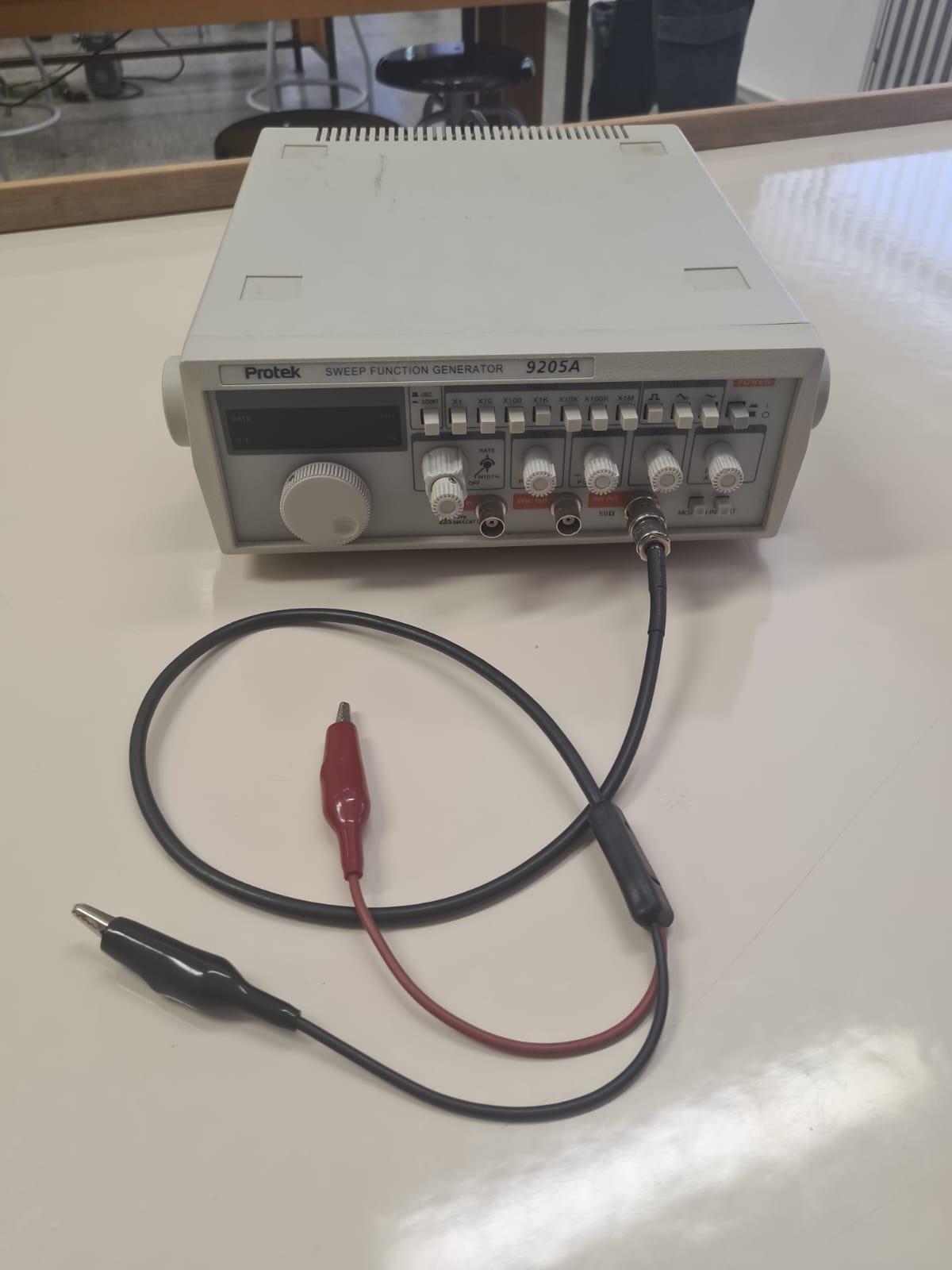
Connect the function generator to the system in series.
-
Connect the probe of the oscilloscope with the resistor, and ground it.
Then we get the circuit:
2.3. Process
-
Set up the circuit. Calculate the area of the plate and note the inductance of the coil and permittivity of free space to later use in calculations.
-
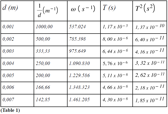
Modify the margin between the parallel plates of the capacitor. Do this for seven different values of d, e.g. d = 1mm, 2mm, 3mm, 4mm, 5mm, 6mm, 7mm. Denote the values d and 1/d in table 1.
-
Tune in the frequency of the function generator until resonance is established, and observe the period with an oscilloscope. Denote T on table 1.
-
Calculate the respective ω and T^2 values for each value of T, denote them in table 1.
-
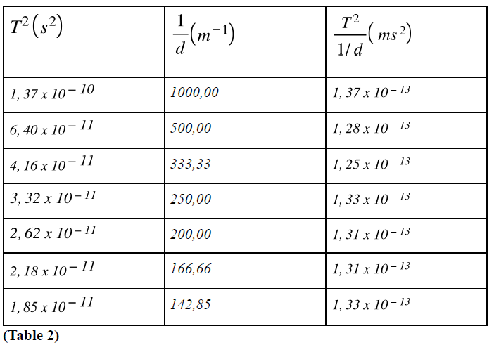
Find the respective (T^2)/(1/d) values for each T and d, and denote them in table 2. This will give us the slope of the tangent line in the graph T^2 versus 1/d.
-
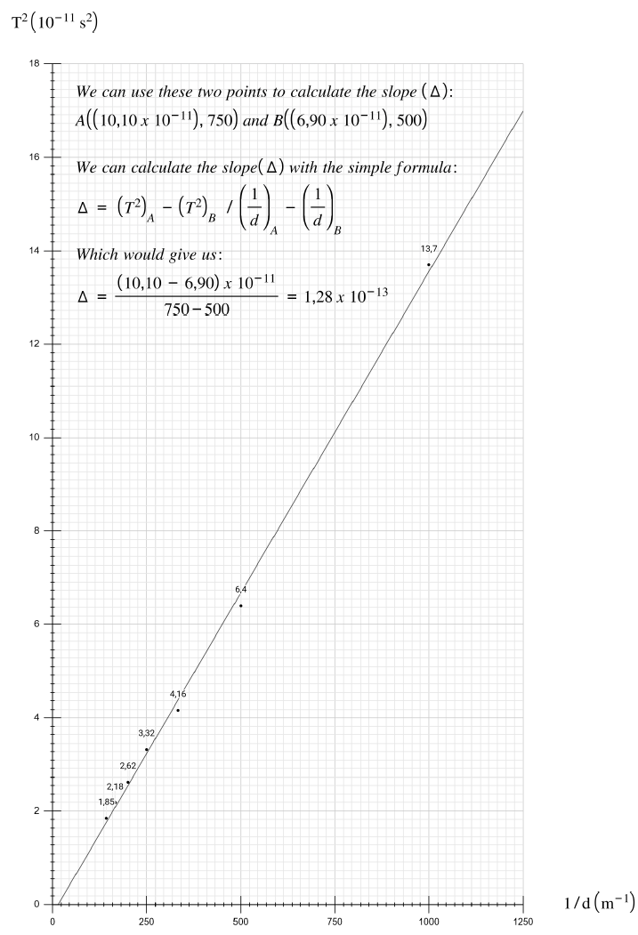
Plot the graph T^2 versus 1/d, and draw the best line.
-
Now, using the slope of the best line in the graph T^2 versus 1/d, find the dielectric constant of the material used, with equation 7.
-
Find the error in measurement by comparing the theoretical and the experimental values of the dielectric constant.
-
Investigate the reasons for such errors in measurements.
3. Data and Results
3.1. Tables
3.2. Graph
3.3. Error Analysis
We can simply calculate the errors in measurements of dielectric constants with the simple formula:
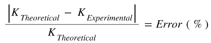
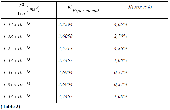
Now, we can calculate the error in measurement for each value of and denote them in table 3, considering that the theoretical value for the dielectric constant of the paper we have used in this experiment is 3,70.
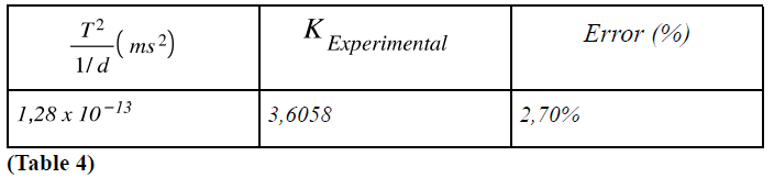
We can also calculate the error percentage for the best line of the graph we have plotted using the same formula, and denote it on table 4.
4. Conclusion
In this project, we successfully demonstrated the resonance behavior of LC circuits, the inversely proportional relationship between resonance period and distance between parallel plates, and we successfully calculated the dielectric constant of paper using the formula we have derived from properties of LC circuits. To achieve this, I used a coil in parallel with a capacitor, and connected a resistor and signal generator in series with the parallel setup made of coil and capacitor. This circuit is the so-called parallel LC circuit. After establishing this parallel LC circuit, I monitored the sinusoidal waves created by signal generator, using an oscilloscope. Then, each time I adjusted the distance between parallel plates of the capacitor, I changed the paper thickness between plates and adjusted the frequency such that the system was in a resonance state. I noted the resonance frequencies and periods in tables, and calculated the respective values of dielectric constant for paper using the formula I have derived from the properties of parallel LC circuits. Then, using a simple formula, I calculated the respective errors in my measurements. The error values I calculated were between 0,27 percent and 4,86 percent, which indicated that the measurements and derivations were on point. Moreover, in this experiment, with the formula derived and the values noted on the tables, I was able to demonstrate that the square of the resonance period is indeed inversely proportional with the reciprocal of the distance between parallel plates of the capacitor. The best line for the graph I plotted for T^2 versus 1/d had a slope of 1,28 x 10^-13 which would yield a value for the dielectric constant of paper, 3,6058 with a measurement error percent of 2,70. These errors in measurements and calculations can be caused by mistakes such as failings while observing the waves in the oscilloscope, minor mistakes while measuring the distance between plates, or they were caused by defects in the equipments used in the experiment. Regardless, as the errors are below five percent, the experiment can be considered successful.
References
Herres, David. “Basics of LC Oscillators and Their Measurement.” Test & Measurement Tips, 20 Nov. 2020,
www.testandmeasurementtips.com/basics-lc-oscillators-and-measuring-them. Ling, Samuel, et al. University Physics Volume 2. 1st ed., OpenStax, 2016. OpenStax, openstax.org/details/books/university-physics-volume-2.
Young, Hugh, and Roger Freedman. University Physics. 15th ed., Pearson Education, 2019.
